A Stream of Consciousness…
A lot of good stuff, but not as much as I’d hoped. The front panel machine work is done for now, ready for my partner in crime, Courtney (N0MJS), to work on making it “pretty”. I can’t easily get to a shipper location during the week, so it is too late get it out until next weekend. Jeff (W3NA) shipped me an RC-96 loaner to aid in my efforts and that was received in good order. First, the front panel…
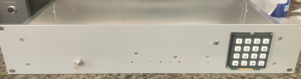
This is a mockup. If you look carefully, you can see the LEDs are placed. The volume pot and reset switch are also placed. The plan, as I understand it, is to print a cover that will span the panel (or a large portion, at least). Part of that, or integrated into it will be a bezel to enclose the keypad, a flip-cover for the reset switch (aptly described to me as a “nuclear bomb switch”, ala War Games), a volume knob (these are so easy to print and get exactly what you want, it doesn’t pay to look for one on-line), and light-pipes for the status LEDs. This is a shot of how I assembled the display:
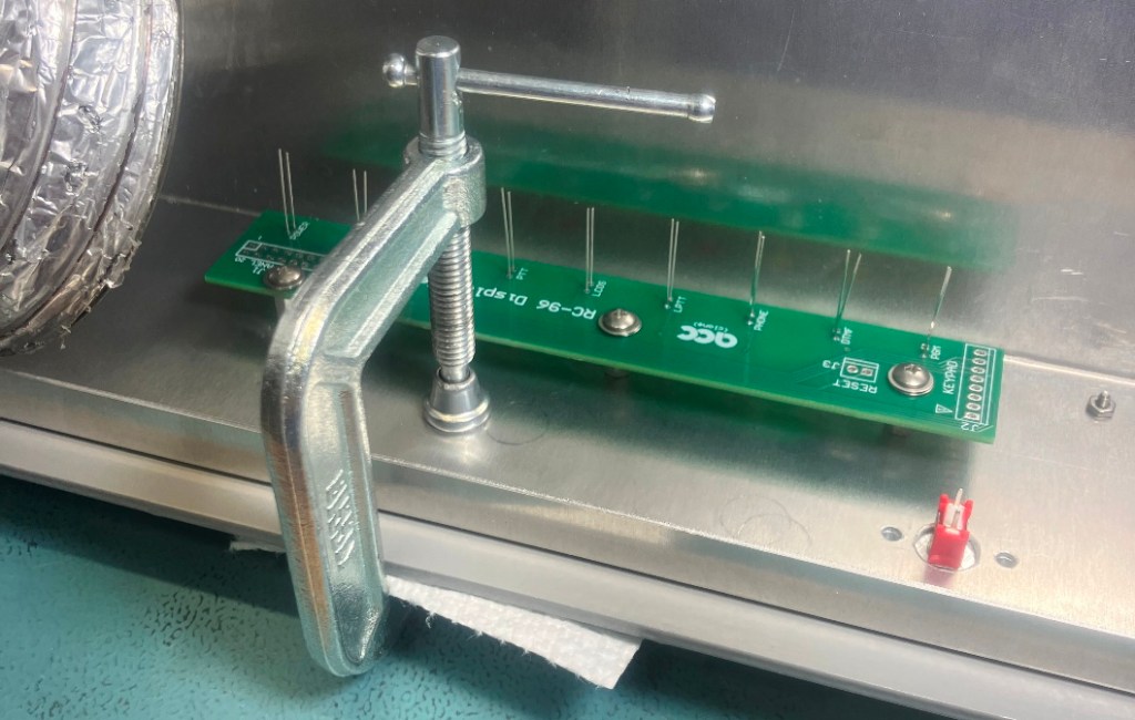
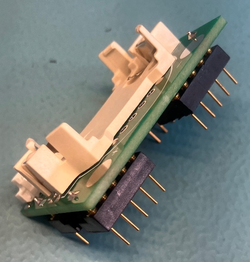
The C-clamp is holding a flat plate over the LED holes so that they end up flush with the exterior surface of the panel. The LEDs are soldered in-situ and then the leads trimmed. Once done, they are exactly aligned (this is the same technique I used for my controller design). The result is small chassis apertures so there is very little RF leakage. With all the connectors are soldered, this is a glancing view of it:
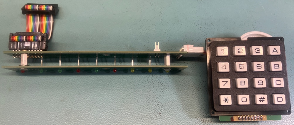
The ribbon cable will match up to the RC-96 front-panel connector, and there will be a short cable for the reset switch. In the above image, one of the spare display PCBs was modified to serve as a protection frame to prevent the LEDs from getting tweaked (I ended up bending a couple of them just in the short time it took me to make the frame). Simple stuff, but did I get all the signals routed correctly? And the wiring of the keypad? One way to find out…
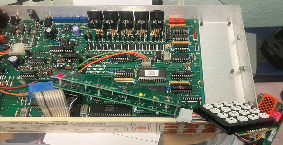
The power LED worked right away. The COS/PTT/DTMF/PGM LEDs have also been verified. The keypad tones sounded correct, but to be sure, I needed to execute the tone-test command. Before I could do that, I had to set it to the default. After a bit of trial and error with the RC-96 DIPSW settings, I finally was able to enter the commands needed. By that point, I knew it was probably wired correctly. Of course, all this was done with my EEPROM installed in the borrowed RC-96 so I can leave Jeff’s data untouched. I will say that my choice of keypad seems pretty decent to me. Soft action with noticeable travel makes it almost fun to key in digits. To be sure, I haven’t yet exercised all of the LEDs yet. There is a lot of RC-96 learning to be done yet…
TK421, DO YOU COPY?!?!?
I have a LOT of gray-market parts cooling their heels in my parts bins for this project. I got lucky the last time I did this for an RC-85, but I’m not so sure I can hope for that a second time. Sure enough, the first confirmed casualty: the 28C64 EEPROM that I bought 2 years ago (way before this project was envisioned). At first, I was concerned that I’d mucked up my EPROM programmer. It is nice to own the design for something, but that also means that there is no 800 number for customer support. It is all on me.
To fault-isolate, I decided to try an SRAM in the programmer. The EEPROM works essentially like an SRAM, except that you have to wait for it to program after writing a byte before you can access it again. The SRAM worked fine (no waiting), so that seemed to vindicate the programmer. The only other EEPROM I had was the one in my RC-85. It is just a “brass unit” that I use if I need to debug another controller, so borrowing the EEPROM doesn’t pose any issues. I’ll order another from Mouser tomorrow and avoid the gray-market on this one.
Several other parts remain, however, so I will probably put some effort into testing as many as I can while I have the loaner RC-96. All this leads to the fact that I ended up testing the SRAMs and at least those are working (tho they were tested on my programmer, which is not a speed-test by any means).
Bond. Galvanic Bond.
I made a point of mentioning bonding resistance in the last post. Part of the front panel effort was to shave off the back-side paint so I can get aluminum-aluminum bonding between the panel and box. With all the mockups, I decided to measure the resistance across the boundary. To do this, I set up a poor-man’s milliohm meter. A 12V wall-wart, a 25 ohm resistor, a couple of DMMs, and some alligator clips were used to set up a 500 mA current source that was conducted across the box-panel interface. One meter measured the current:
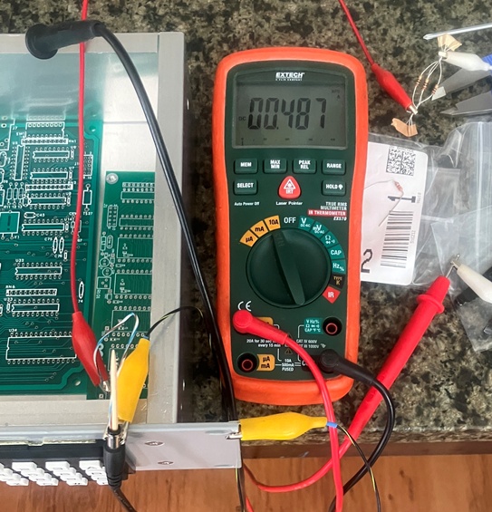
Next, the voltage drop across the boundary was measured. By measuring the voltage away from the primary path of current flow, all (or at least, most) of the resistance in the path of the current source is eliminated (this is known as a Kelvin connection) allowing a very precise calculation of the resistance across the gap. Here, the voltage was so low, that I had to round it up to be sure I accounted for any resolution errors that would give an over-optimistic result:
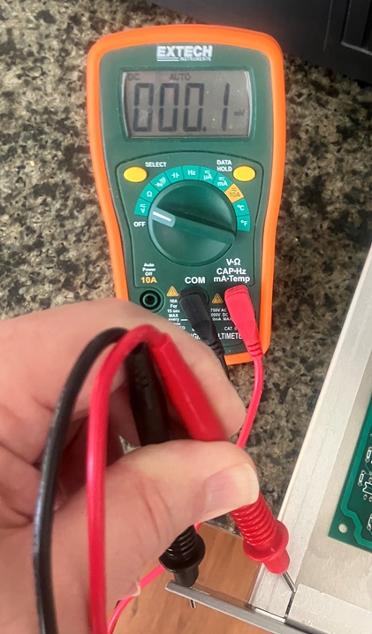
So, 487 mA and we’re calling it 200 uV. Note that the current path is primarily situated on the opposite side of the chassis. This calculates to about 0.4 milliohms, about 1/6th of my 2.5 milliohm target. So, I am not worried about that issue any longer, but I will still likely check it again during final assembly.
You ALWAYS have to drag that infernal 3D printer into EVERYTHING, DON’T YOU!
I’ve been using Aries headers for my interposer assemblies. They are decent, but there are two annoyances that come with them: 1) They are pricey. The 28-pin versions are almost $5 each. 2) They fit a little too snugly into the machined-pin sockets. One must apply a great deal of force to insert and remove them.
I was casting away on the internet and found a surplus store that had just what I wanted. Small diameter, machined header pins that were a better fit into the machined-pin sockets used on the RC-96. Problem was, they were only 24 pins. I reasoned that I could cut them to 14 pins and mash two of them together to make 28 pins. Less cost, better performance, but the price was in making the saw-cut. My first (free-hand) attempt was mediocre at best, so I decided what I needed was a miter-box that accepted my headers and razor saw. That’s right kids! It’s 3D printer time! This is the view of the miter-jig in the slicer:
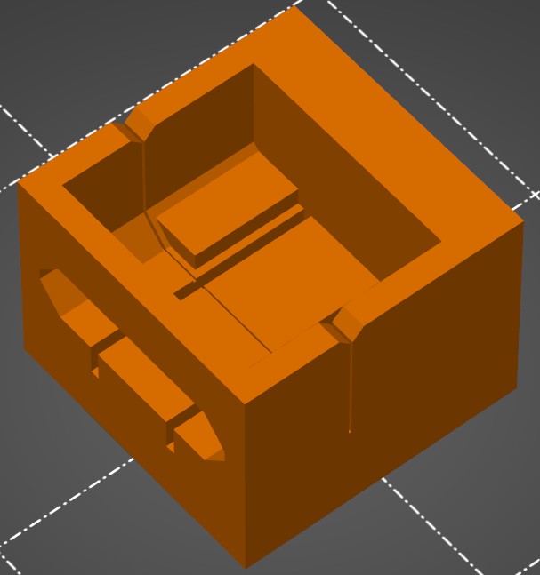
If I got the dimensions correct (never a sure bet), the header will slide in from the side, and the perpendicular slot will allow the razor saw to make a precise and repeatable cut. It will take just over 3 hours to find out. Actually, it will print overnight, so I won’t find out until tomorrow. If not, I will tweak it and try again.
The leftover pieces can go into the coin-cell battery holders (not that I expect to find many takers for them):
Go forward, or Move Ahead…
There is still a bit of machining to be done. I at least need to get the template for the back-panel finished in case my loaner RC-96 gets recalled. But I am ready to do some serious soldering, so I may pivot a bit and work on the tone panel. I also need to read the RC-96 manual. Most of my interactions with the RC-85 were simply to figure out the minimum that I needed to know to get one command to work, then on to other things. The tone panel alone will require more than a passing understanding, much less the other stuff going on in there. Once in a while, we have to avoid taking the tldr way out and just R-T-F-M.

Leave a comment