This week is mechanics week. I finally got a chance to work on the drilling template and check some other boxes. I’ve been at this for a couple of months now, and it still seems like I haven’t even started yet.
Seize the Day, er Threads
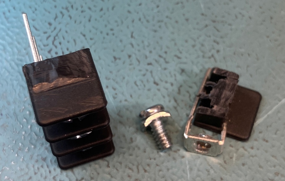
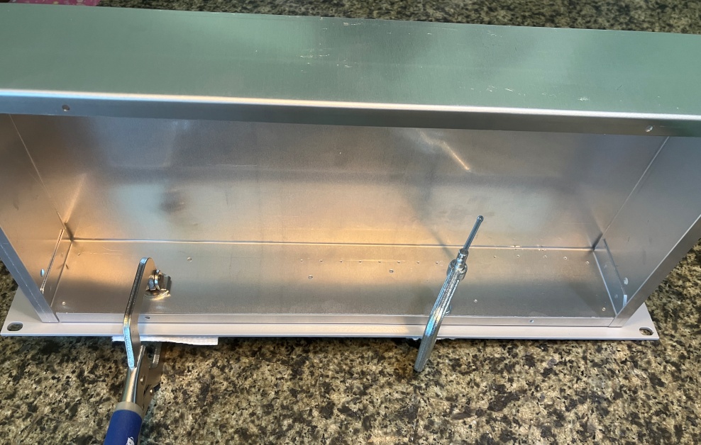
First, the terminal block. The RC-96 features a 3-position terminal block to connect earth ground (for TELCO) and a back-up battery (if desired). I found a nearly identical block that was 4 positions made by Eaton. I bought it from a reputable dealer and it sat in a bin with a lot of other parts for the last few weeks. I decided to trim off the extra position as part of this weekends festivities. But wait, like everything else in my life, it just CAN’T be that simple…
I wanted to get the screw out of the way on the end position, but they were jammed in really tightly. Only, they weren’t fully seated. In fact, they weren’t even close! Turns out that all 4 of the screws were nearly seized in place and were VERY difficult to remove. It was clear that no reasonable amount of force was going to allow them to be fully seated. I examined the threads on the screws and 3 of them were not too far gone and they exactly matched a 6-32 screw that I pulled out of one of my hardware bins. The 4th was really rough looking. I don’t think I would like to have to trust it.
Using a toothpick, I tried to take an impression of the female threads. Best I could tell, they looked to be M3.5-0.7, but there is a lot of room for error in that. I know that M3-0.5 screws were too small, but I have no M3.5 screws to try. Ultimately, I just chased all of the threads with a 6-32 tap and that allowed the 3 “good” screws to work.
Before I worked all that out, I did a quick search on ebay. After a lot of scrolling, I located these:
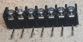
These have the added advantage that I can part-off a 5-position block and use the 2 end positions as mounting points to the chassis. IMO, this would be a lot more robust than just allowing the terminal block to be supported by the solder tails and the PCB PTH structures. Not stock, but I’m not afraid to improve on things a bit. These are another week out so we’ll have to wait and see how they look once they arrive. Plan B sometimes ends up being plan A.
A Template for the Ages
As mentioned previously, I need a template for the RC-96 mounting holes before I can start assembling the PCB. I found a scrap of 0.04″ aluminum in the garage and proceeded to turning it into just that. I spent a lot of time trying to get a straight edge on the back-side of the template. I even looked into using the mill-lathe but I was reminded of one of the painful limitations of my machine. While it has a 40″ lathe bed, the movement under the mill-head is limited by its proximity to the lathe head-end. I couldn’t run the nearly 16 inch length of the template without removing it, flipping it around, and then trying to get it re-aligned. I had to do my best with a file and a piece of angle-aluminum as a straightness gauge. Definitely not optimal, but good enough (or so I am reporting).
I used the PCBs (RC-96 and Tone Panel clone) to transfer hole locations directly to the template. Careful application of a center punch and equally careful drill press activity produced a reasonable set of pilot holes that can either be transferred by tracing, or by direct drilling (preferred). This photo doesn’t really impart much sense of action, but it represents a few hours of effort.
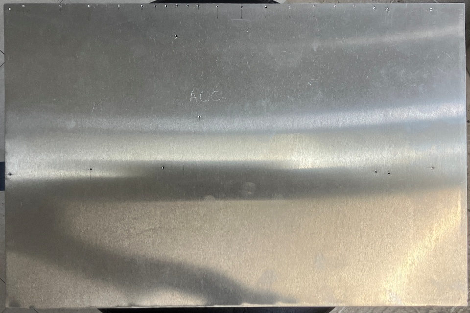
The extra holes along the back edge (top edge in the photo) locate the connectors and other items that need to align to openings in the back of the chassis.
The bottom edge in the photo will be used for the back panel template. My plan is to use another borrowed chassis to transfer the hole locations and sizes so that is on hold until I get my hands on one again.
Electro-Mechanical… it’s still MECHANICAL.
I did do a little soldering. Several interposers were planned for this project. Some, like the address decoder plan-B, are moderately complex. Others are very simple. The battery holder and TLC14 SOIC-DIP adapter fall into the simple category. BTW, the TLC14 is a substitute for the IR1005 at U35 and 36. I expect it to work, but testing will prove that one way or the other.
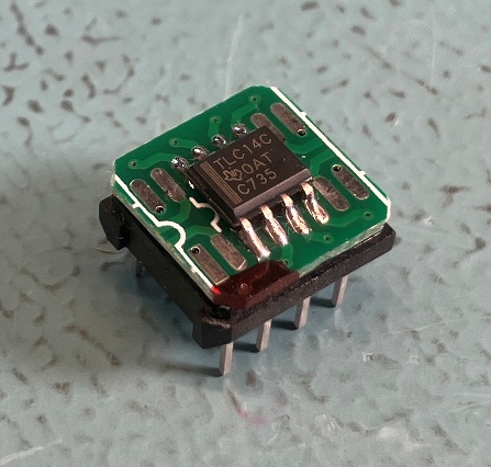
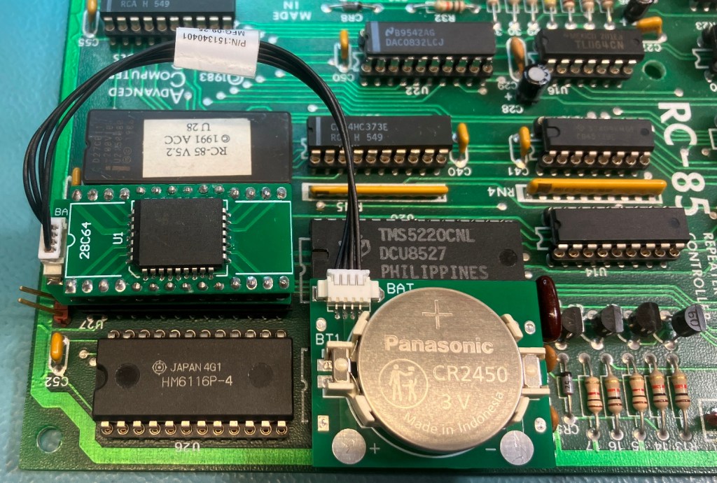
The battery holder is to be plugged into an unused, 28-pin DIP socket on the controller (U34 on the RC-96, with my RC-85 illustrated above). There are no electrical connections to the 28-pin socket, it is just a mechanical interface to secure the battery holder to the controller PCB. A short cable connects to the smartwatch clone (which is hidden by a PLCC-DIP adapter for the EEPROM).
Finally, the decoder anti-“oh-$#!%” adapter with the decoder interposer:
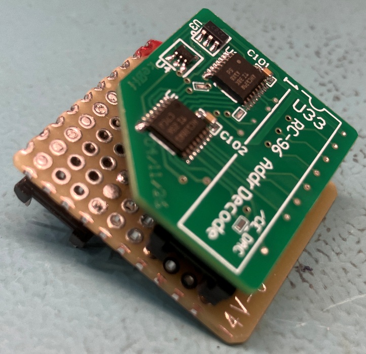
Here, a “dog-leg” adapter is used to shove the decoder plan-B board over to the side, away from the spot where the battery holder will be situated (see the next photo). These are two adapter/interposer boards to do the work of one (nice work, if you can get it).
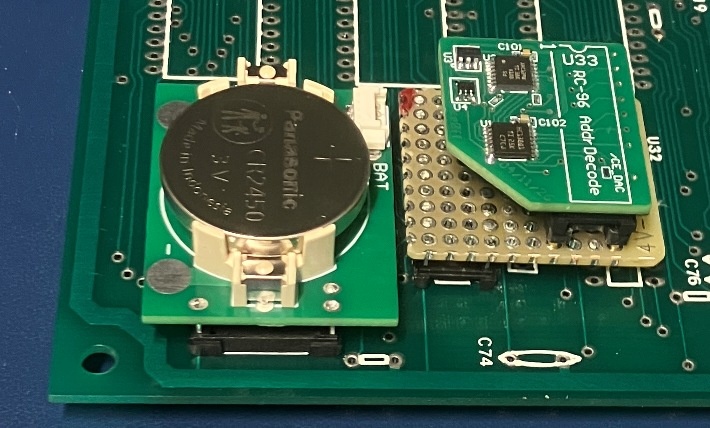
The result is admittedly ugly, but it should work. At least, it will work until it doesn’t…
Front (and as “center” as you can manage)…
The front panel is the next priority. I need to get it prepared so I can send it to a friend of mine for painting/striping and getting a bezel designed and printed for the keypad. I may not get this done this weekend. As I type this mid-Sunday morning, I am contemplating all that needs to be done and I’m getting a little freaked out. First, there are some questions. Such as, make a template or go direct to the chassis and use that as a template for the front panel? The front seems simple enough, but it is really a bit busy up there.
Foremost, and something that gets less traction that it should, is that holes are needs to secure the panel to the chassis box – I like to place at least 6 of these. Next there are the holes for the LED board, both mounting and for the LEDs themselves. This pattern needs to align to the RC-96 connector so that there isn’t a significant left-right deviation to the cable connection. The volume pot needs similar attention. The keypad has 4 mounting holes and a slot to pass the wires that connect to the LED PCB. Last is the reset switch.
I also like to add “ears” to the bud-box contraptions. This is little more than a piece of angle aluminum that fits into the corner of the chassis box and the front panel edges, one on each side. These help transfer the torque that results from the cantilever arrangement formed by the panel and the chassis box (which is generally only supported by the front panel). These pieces are simple, but there are a lot of machine operations tied up in their construction so they can easily take a couple of hours to complete.
Lastly there is the grounding conundrum. The Bud panels are painted (but not in the color we want). If you are installing something into a known hot-spot for high-rate EMF surges (e.g., lightning) you really need all of the pieces to be electrically bonded to each other in a manner best summarized as “very well”. This is more than what a simple DMM ohmmeter measurement might reveal, it needs to be something less than 2.5 milliohms. To get this, you need lots of surface area between adjacent pieces. So, in addition to all of the above, I will need to figure out a way to improve the bonding between the panel and the Bud box and also between the panel and the rack. This is probably little more than some spot-facing operations on the mill, but that is another hour of setup and execution to factor it. I may need a week of Sundays to get this panel done.
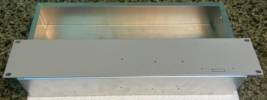
Here is the front panel lashed to the Bud box just before the hole locations were transferred with a fine-point sharpie:
Here is most of what I got accomplished so far (counter-sinks not shown and keypad slots have yet to be cut):
Good Night and have a Pleasant Tomorrow…
I managed to get the pilot holes cut on the front panel and chassis front. I also got the panel mounting holes drilled and countersunk. Almost ready for a mockup/test-fit, but that will not happen until next weekend. Overall, a reasonably productive weekend. Here’s to many more.

Leave a comment