Lots of activity of late, but perhaps less progress than I might have hoped. I got the “other” projects off my bench, so now I appear to have even more time… that I don’t have. Still, I was able to work on a couple of aspects of this project, both relating to device programmers.
One of the most crucial aspects of this project is programming the address decoder PAL. There are hundreds of signal combinations possible with even the simplest implementation of this device, so it would be difficult to hack. The current ACC IP holder has a fuse file for this device available for download. It is a standard file format that is viewable in a text editor which appears to be valid based on my rudimentary examination. That file is a key component to the success of this project.
I have a device programmer, but it supports neither the GAL nor PAL devices, nor does it support the 27×011 EPROMs. Two years ago, I sat down and built an EPROM programmer from scratch (see GitHub – ke0ff/FFPGMR: EPROM Programmer, MK-II · GitHub) specifically to support the strange (to me, at least) EPROMs that ACC used. I figured that step was covered, at least. But nothing is ever as it seems…
Turns out, I had noodled on the programmer software and broke the EPROM algorithms. The FLASH and other algorithms still worked, but not the EPROMs. This at least gave me a path to programming the RC-96 main program memory (using the previously mentioned interposer). Not the path I wanted, but a path that would work.
After spending most of my Saturday on the issue (and several days of contemplation prior), I was finally able to get my programmer to write data to EPROMs again. Some victories are small, but we take them anyway.
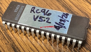
27C010 EPROM (to be used with an interposer on the RC96)
Back to the GAL/PAL… I borrowed a GALEP-III programmer, it lists the GAL16V8 as one of the devices it supports. I felt confident that I could build an add-on to my EPROM programmer that would support these devices, but time is irreplaceable, so I opted to avoid the effort. The programmer is hosted on a very aged WIN2000 laptop, but the whole smash booted and appears to be functional.
Transferring the file was a bit of a chore. While the laptop was apparently able to connect to the modern internet, I did not want to go down that rabbit hole. 3.5″ floppy was the obvious choice, but the drive for the WIN2000 PC (which emitted a nasty noise while operating) wouldn’t read my disk {pause for calm reflection…}. I found a null-modem serial cable (like, RS-232 serial) so we went really old-school and I used serial transfer protocols to get the file moved into the WIN2000 PC file system.
The devices programmed and verified. All too easy, or was it? Trying the devices on my borrowed RC-96 was disappointing. Nothing happened. I even fetched some other GAL parts from ebay (from a very different seller) and they responded in kind. According to the programmer, they were fully programmed and verified. I even tried “de-programming” them by applying all input combinations and capturing the outputs. There was no variation in the outputs. Not good.
So, I decided I might have to engineer a GAL programmer after all. I now have most of the support hardware complete.
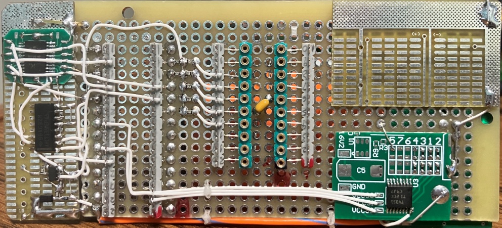
The circuitry on the left is the “autoselect” driver. This allows the programmer to identify the adapter using the same techniques it uses to identify memory devices (by driving A9 = 12V and reading the code at addresses 0 and 1). The adapter provides the code “BE EF” which happens to violate parity for the device codes (meaning, no other device will conflict with it).
Bottom right is the voltage select MUX which provides a series of selection resistors, via an analog switch, to the boost supply on the back side. This allows the adapter to support 4 different EDIT voltages between 12 V and 16 V. The DUT to be programmed goes in the center socket. All that remains is a switch for the EDIT voltage and the minor task of software to support it. A job for another weekend.
Other news…
I pulled the trigger on the PCBs for this project, 7 in total. At $45 for shipping, I decided to take the slow-boat from China method, which cost only $10. The catch is, I might have to wait another 2-3 weeks for delivery.
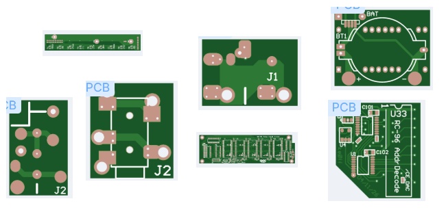
Montage of the custom PCBs for this project
One new item is the smartwatch battery holder (upper right in the montage above). This was a last-minute idea to address the question of “how/where to mount the battery for the clock interposer?” The idea would be genius if it hadn’t taken several years to come up with it. The solution is to use the un-used IC socket at U34 to hold an interposer for the over-sized coin cell battery holder. The interposer doesn’t electrically connect to any of the U34 pins, it just serves as a mechanical attachment. The battery connects to the smartwatch clone via a short cable. We’ll see how it works once I get the boards.
I also got the new keypad candidate:
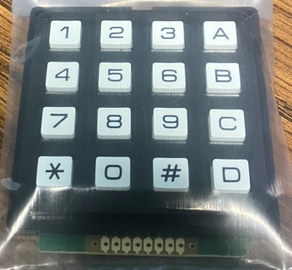
I like it a LOT more than the membrane types.
Next steps are:
1) Keep driving the GAL/PAL crisis until the PCBs arrive.
2) Start cutting mounting and access holes for the chassis
3) Wait for the PCBs to arrive…

Leave a comment