The Last RC-96
Recently, a friend advertised an RC-85 for sale “without IC’s”. My interpretation was that the controller had seen a bit too much lightning, and the IC’s had been removed in hopes of replacing them all, and that just never happened. I had done just that for someone’s RC-85 a couple of years back, so I knew it was at least possible to find all the parts. So, why not? I decided to give it a shot. After a short time, I got a package in the mail and upon opening, this was revealed:
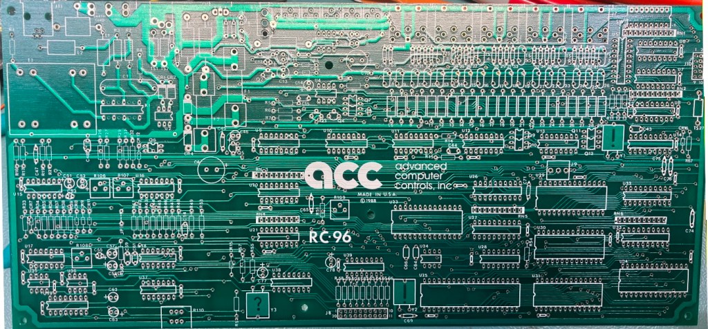
Er… NOT an RC-85! Also, not just missing IC’s, but missing EVERYTHING! After about 2 ms (that is 0.002 seconds), I realized something terrible… I was about to build an RC-96… from SCRATCH!
First, Some Background…
For those relatively new to Amateur Radio (as in, licensed less than 20 years), ACC may be unfamiliar. Advanced Computer Controls was arguably the company that brought repeater controllers into the 20th century. Microprocessor control, speech synthesis that was intelligible, lots of programmable features. Their controllers were the ones everyone wanted. They weren’t cheap, however, causing many to choose cheaper alternatives. Few would rival what they accomplished. The RC-96 was the last model to be released and featured a number of improvements over the previous models. Many are still in service even though their age makes it difficult to obtain service or spare parts.
I love the smell of a new project in the morning…
Right off the bat there were questions. Can I get the ICs? Connectors? I have a box of phone-line transformers for the repeater controller I designed (the FF-800)… it would work, but it wouldn’t “look right”. Turns out, one of my older controllers used the same brand as the RC-96, but slightly different part#, so I decided to salvage it for this project. For the ICs, I started with the schematic and made a list of the parts I knew I couldn’t get easily, or that I couldn’t identify. After trolling ebay for a while, I was satisfied that I could get all of the parts that I could identify, which just left a couple in the audio section.
The connectors were a bit more tricky. They generally don’t have part numbers stamped on them, and a given connector can come in many flavors. I found a terminal block that was a close match for the battery connection. It is 4 positions, so I will have to shave off one of them to get it down to 3 positions. I finally found DIN connectors that appeared to have the correct footprint on ebay (I was really sweating this one). Having just gone through a similar exercise for my controller, I had a few RJ-11 connectors that I purchased looking for a replacement for my “Last FF-800” project (which, coincidentally, I am just about to finish as I started this project). Turns out, one of those was a fit for the RC-96. That just left the speaker and power connectors. No luck yet. I have a plan for these two connectors, but more on that later.
The loan of an RC-96 from another friend of mine allowed me to identify all of the questionable parts and come up with reasonable substitutes. My goal here is to make this controller as close to stock as is feasible given that 30 years have gone by and many of the original parts manufacturers aren’t even in business anymore. So, where it is not possible to *look* stock, I will be satisfied if a replacement part provides the same function as the original.
There are still a few open questions, but I think I have answers for most. Such as, what about the Smartwatch clock socket? These are (were?) available on ebay, but it is arguable that most of them are over 10 years old and thus the batteries that are embedded within are well past their shelf life, even if they haven’t ever been used. Fortunately, I designed a replacement that features an external battery which solves the battery problem now, and forever. All I need is a defunct Smartwatch (defunct in that the battery is dead or suspect, but the clock still works if normal power is applied). As it happens, I have a couple of these in a box somewhere.
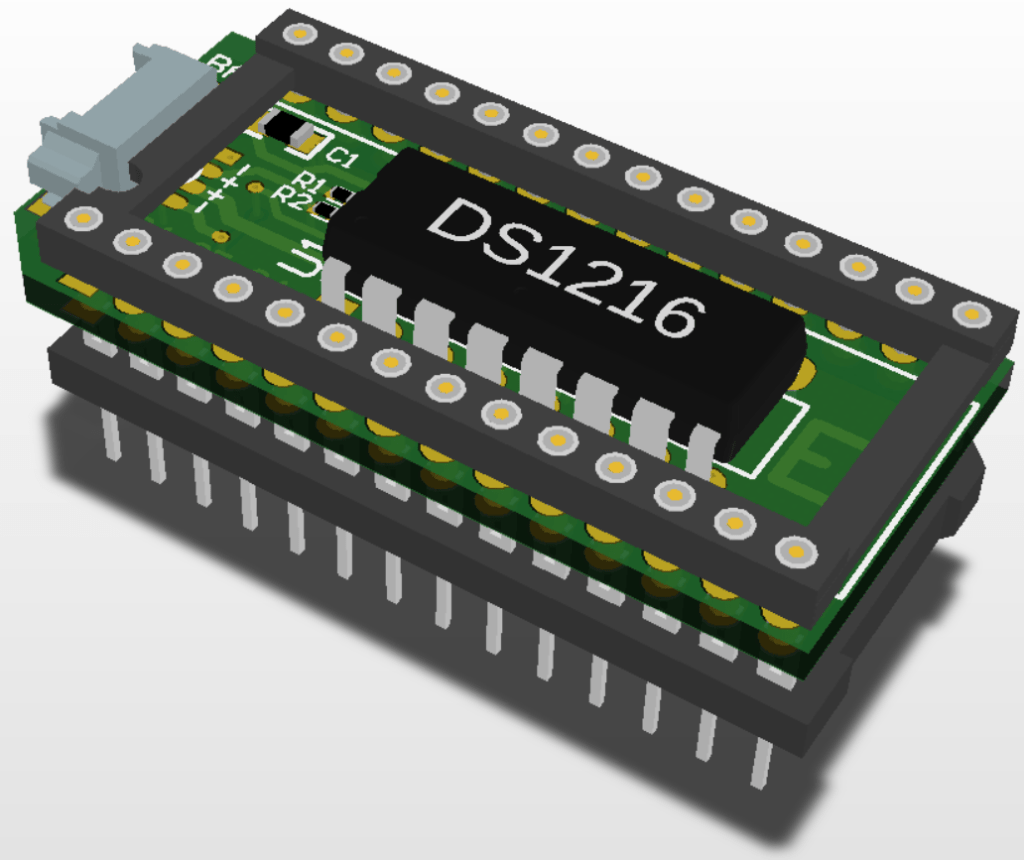
3D CAD view of my SmartWatch solution
The EPROM is another conundrum. The 27C011 used in the RC-96 (and RC-85) is a bank-switched device that had a brief run in the marketplace (along with the smaller 27C513) allowing folks to expand their existing designs without a new PCB (interestingly, the 80’s and 90’s vintage video games were a big consumer of these parts). However, these parts were more expensive than standard EPROMs, so new designs didn’t use them. As a result, not many devices were made compared with standard EPROMs of the same density, and not many programmers support them. To solve this, I did two things: 1) I built my own EPROM programmer so that I could read/program the 27C011 and 2) I designed an interposer that allowed a standard 1Mb memory (FLASH or EPROM) to be used in a 27C011 socket.
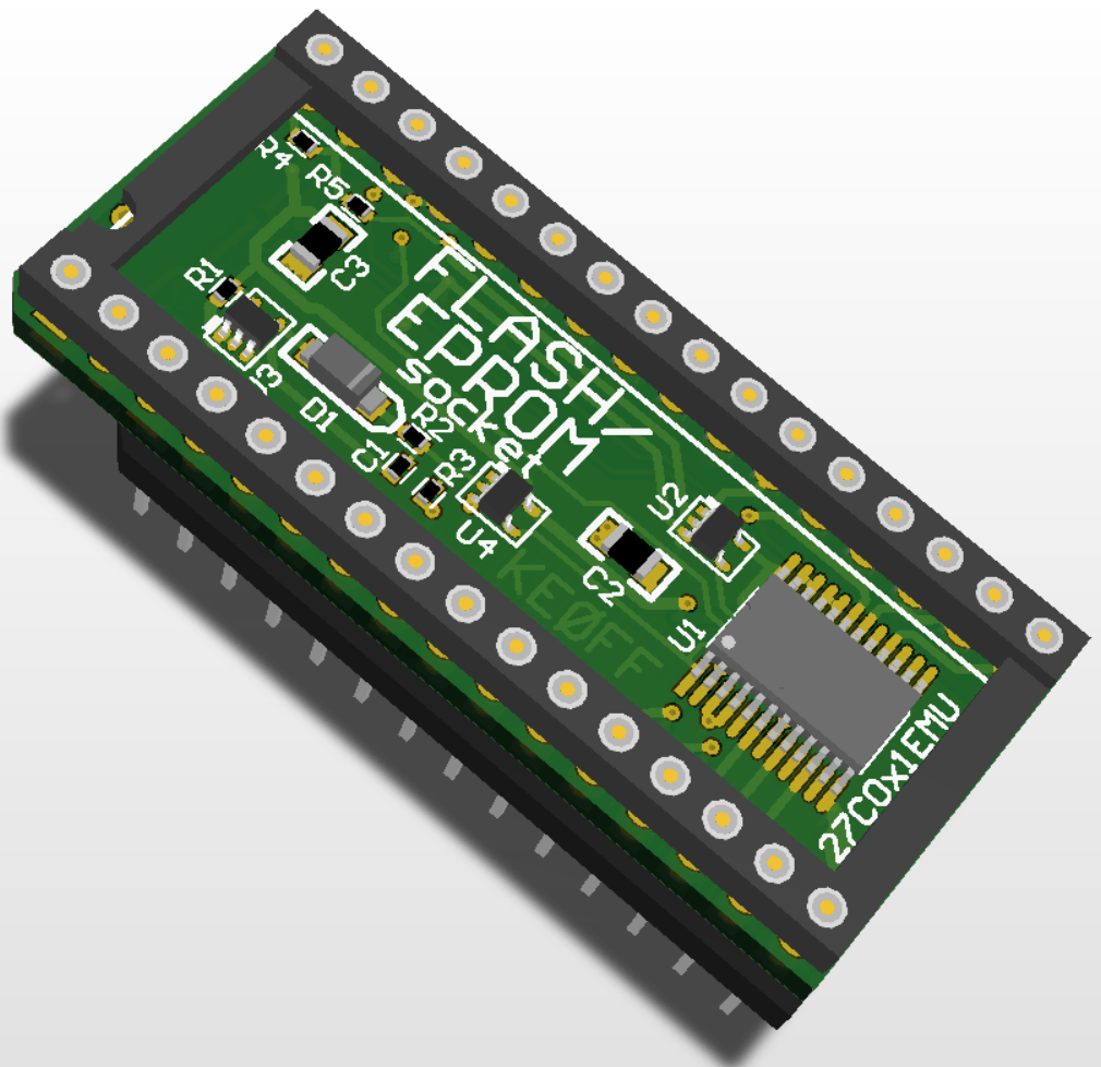
3D CAD view of my 27C011 EPROM Emulator
The last IC in question is the address decoder PAL. I found a copy of the V5.2 EPROM object on the internet. Included was a JEDEC fuse map for a GAL16V8. This was a different device from the PAL10L8 that is on the borrowed RC-96 which has a V5.1 EPROM. Did they just switch to the GAL parts because they were more available, or because they wanted to copy-protect the V5.2 object? In either case, I didn’t really have anything that would allow me to program GALs or PALs. I did find some documentation produced by an intrepid soul which looks to be sufficient enough to allow me to modify my EPROM programmer to program GAL16V8 parts. A project within a project.
And then… depression set in.
I’m staring at the borrowed RC-96… I came to the realization that this project was going to grow. There was no avoiding it. The CTCSS panel was mocking me. I was going to have to make one of those too. A project on top of another project… within a project. I couldn’t find any MX355 parts, however. Nutt’n. Zip. NADA. Fresh-out! However, I found a source of some MX365s. They appear on the same datasheet as the MX355, and perform the same function, but have a different package size (the MX365 is bigger than the MX355). I was going to have to layout a new PCB for the panel anyway, so I can just design this new PCB to accept the MX365 instead. It won’t *look* exactly like an ACC tone panel, but it will work the same.
The last big conundrum… the CHASSIS. Making a chassis identical to the ACC chassis is certainly possible, but at no small cost. I’m not going into this as a business, so I am not going to be able to amortize out the non-recurring costs of having sheet metal work produced. I might invest half the cost of a brand-new (back in the day) RC-96, but not 3x or 4x.
This leaves the good, ole, Bud box chassis pieces. Problem is, they have limited combinations of length-width-height. In addition, in order to provide a keypad, I would have to get one off-the-shelf which won’t match the ACC form-factor. The chances of finding something even *close* to the RC-96 keypad is very remote. I could get one made, but again, a lot of cost that I won’t be able to capitalize on. So, the resulting chassis will definitely look like a garage-shop creation. While unfortunate, it will be functionally equivalent which is good enough for this garage-shop.
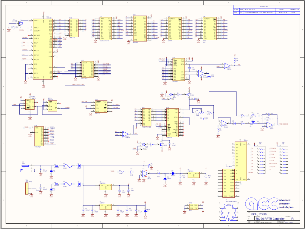
At the moment, I have about half the parts for the RC-96 (the hard-to-get half). Next, I am re-doing the schematic in my schematic capture-tool-of-choice (Circuit Studio, A.K.A Altium-Lite). There are a couple of reasons for this. One, the original is very difficult to read. If I were to have an actual, original, paper copy, it would likely STILL be difficult to read. More importantly, I need a parts list. The schematic is a great way to capture that information while producing a readable schematic (which will be made available to repeater-builder once complete). While I am at it, I can also compare the schematic against the PCB to make sure it matches the PCB. BTW, I will also have to do this for the tone panel. In this case, I will need the schematic to allow me to generate a PCB. Here is a sneak peek at page 1 of the new RC-96 schematic:
Hold your horses! (seriously, they are getting away from you!!!)
I was going to wait on the tone panel. Pace myself. Savor it a bit. Now, barely a couple of weeks in and I am well into the layout step. I wasn’t able to fit 8 MX365 parts into the available board space, so I had to settle for 5 (I have enough parts to fill 4 of those spots). Placement is roughly following the original. However, I am using SMD parts to help save some space.
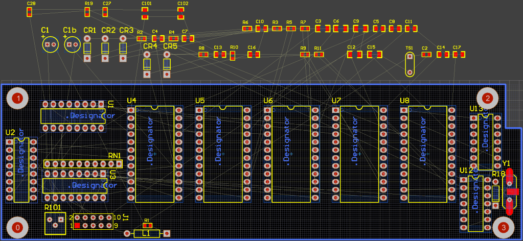
Given a couple of hours, I will have the placement complete. Then, it almost routes itself, assuming the placement is decent. So, I am WAY ahead of schedule on this part of the puzzle.
Family obligations loom. It will be a bit until I make more progress. At the moment, I have most all of the critical parts. The “chicklet” parts (resistors and caps, mostly) and a few ICs that are readily available remain. Once I get the connectors all figured out, I will make one last Mouser order to finish off the last of the needed parts, leaving just the soldering exercise. That is the plan for now, at least. The blog posts below detail my progress going forward…
